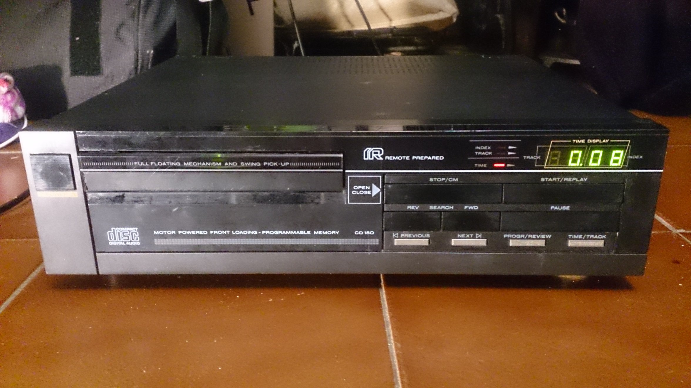
Reparei este leitor de CDs vintage (com o aclamado DAC TDA1540) que me foi parar às mãos muito baratinho e sem tocar um único CD (dava mensagem "ERR").
Problema: não tocava, dava mensagem ERR.
A primeira coisa que fiz foi abrir e limpar a lente do laser. Não resolveu. Peguei no meu smartphone com câmara e fiz um pequeno "filme" da cabeça do laser ao carregar em "Play". Boas notícias: via-se claramente o ponto vermelho de luz do laser e a lente a mover-se várias vezes para baixo e para cima (focus), portanto o laser e o mecanismo de focagem estavam funcionais.
Descobri por acaso que por vezes tocava um pouco e com dificuldade quando fosse deixado ligado bastante tempo para aquecer.
Fiz download do Service manual (um dos melhores sitios para isso na Internet é HifiEngine) e segui as instruções de diagnóstico: quando posto no modo de manutenção (service position), ele ia até posição 2, falhando na 3 (só passava para esta muito raramente quando já estivesse ligado muitas horas).
Comecei as medições, de acordo com os test points mencionados no manual. A voltagem do laser estava perfeita. Medi então as tensões de alimentação e fiquei baralhado (era o primeiro CD150 que estava a reparar): não havia +-9V, mas sim +12 e -13V, bastante elevados, pensava eu. Mais tarde cheguei a medir mais leitores dessa gama e têm todos essa "falha" de design: voltagens não reguladas demasiado elevadas. Por isso, não façam como eu fiz aqui, perdi tempo tentando medir o transformador e até construí e instalei temporariamente um pequeno circuito regulador de tensão à base de LM317/37, só para verificar que não alterava em nada o comportamento do leitor e os reguladores aqueciam, teria que usar um heatsink enorme, desisti da ideia e percebi que estava a perder tempo.
Solução:
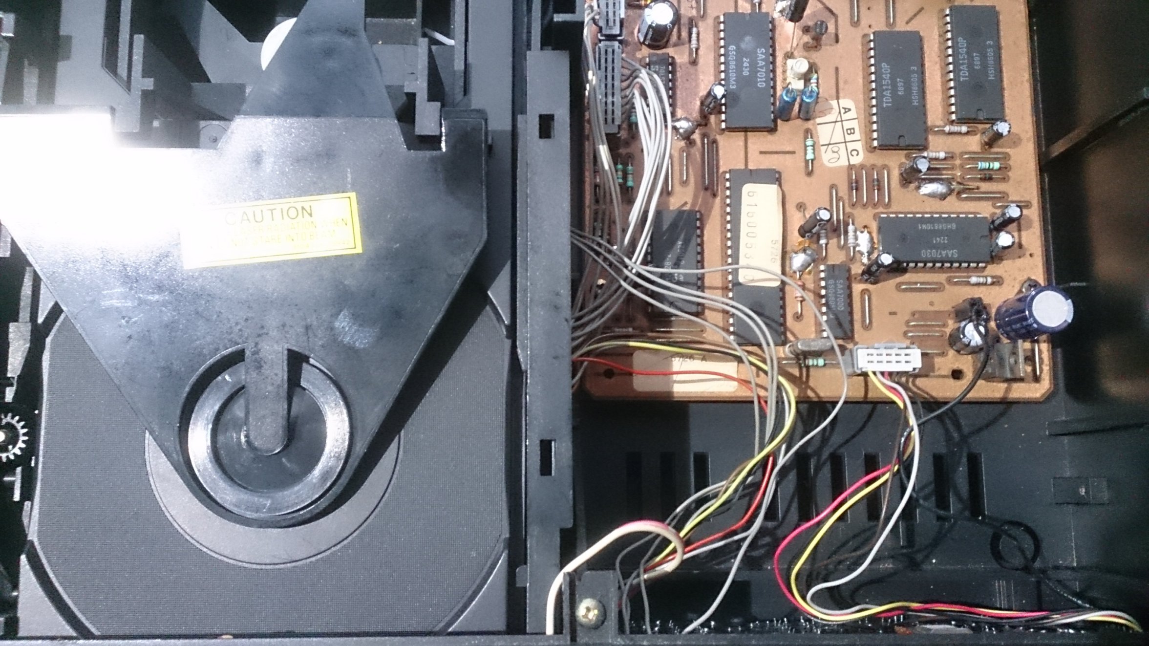
o problema foi difícil de localizar (descobri por acaso que começava a ler quando estivesse ligado muito tempo) e acabei por fazer várias coisas a este leitor, mas julgo que o principal problema fossem os chamados "griplets", pontos de solda grandes que a Philips usava para ligar o plano inferior da PCB ao plano superior. É um problema conhecido (ver por exemplo este link) - estes começam a oxidar e a quebrar a solda com o decorrer dos anos e deixam de fazer contacto, causando toda uma série de problemas que por vezes melhoram temporariamente à medida que o aparelho é deixado ligado para aquecer (pois começa a fazer mais contacto). Optei por não furar nos tais "griplets", como recomendam para o CD104, pois aqui havia sempre o perno de um componente no meio do "griplet", por exemplo de um condensador, então limitei-me a chupar com uma bomba de dessoldar a solda existente, raspei o cobre do plano de massa de cima para ficar brilhante sem oxidação e apliquei novamente muita solda para fazer bom contacto, também no plano de baixo.
Também substituí praticamente todos os condensadores electroliticos, talvez tenha sido também um condensador defeituoso. Os leitores Philips antigos sofrem muito de um problema da avaria de um condensador electrolítico importante no circuito de alimentação do laser (aqui é o C2103 - entre a base do transistor driver do laser e massa, para filtragem), trata-se de electrolíticos de uma gama particularmente má e de fácil degradação com o decorrer dos anos (são azuis, axiais, são da própria Philips, até podem medir perto da capacidade original, mas é sempre melhor substituir. Tem havido muitos leitores que já não liam nada e substituindo esse condensador voltam a funcionar).
Tive ainda de cortar o conector e soldar directamente os fios de um dos conectores da placa do display/controlador, visto que fazia mau contacto e o conector já não estava bom, um problema clássico nestes leitores com o tipo de conectores usados, a alternativa seria arranjar um conector e cabos novos, mas é muito difícil.
Falta ainda mencionar que tive de lubrificar todo o mecanismo da gaveta e substituir a correia, e optei mesmo por reduzir um pouco a tensão da mola daquela estranha "porta" que estes leitores tem, pois a gaveta encalhava nisso. A gaveta dos leitores baseados em CDM-2 costuma dar muitos problemas, por vezes não se resolvem só com uma nova correia.
O único upgrade que fiz com este leitor (pois era para despachar) foram condensadores de maior capacidade na secção da fonte de alimentação, mas estes leitores têm bastante potencial para mais mods e upgrades: podemos instalar melhores opamps de saída, melhores condensadores de filtragem nos CIs digitais e na secção do servo, idealmente instalar reguladores de tensão para criar alimentação limpa dedicada para o DAC e para o SAA7030, e existe ainda a possibilidade da Non-OS-mod (desactivar o oversampling), com tudo o que isso implica de bom e menos bom. Mas como o leitor já "de origem" soa bem e era para despachar, não fiz nada disso.
Fotos:
==========================
English:
I got this nice little vintage player (based on well known DAC TDA1540) very cheap, with the problem: the player wouldn't read anything, showing "ERR".
First things first - I opened it and cleaned the lens. Nothing improved.
I then took my mobile phone camera and "made a movie" of the laser lens when hitting play. It showed that nice tiny red dot and also the coil moving up and down, so laser and focus was working.
Next, I got the service manual (one of the best places on the internet for this is HifiEngine) which describes how to access the three service positions. Tried them out and the player clearly passed stage 1 and 2, but then, the number 3 would sometimes appear very shortly but it would immediately stop and go back to 0. Sometimes even with the swing arm making a hard stop against the limit.
I tried the Fast forward and Backwards keys to move the swing arm, responded well.
I starting measuring at test points mentioned in Service manual, laser voltage was fine.
Measured all supply voltages and got kind of confused, this was the first CD150 I was repairing: it didn't measure +-9V, but +12 and -13V, which is very high for CDM, I thought. Much later I had the chance to measure other similar players and all of them have high voltages, as they're unregulated, it's basically a design flaw, but it's not really severe. As I didn't know this, I thought there could be a problem with the power supply (transformer showed signs of aging, humming very audibly), checked all, even changed the supply wiring to 240V (was 220V), didn't make a change, then I even built a little regulator circuit with LM317 and 337 to feed clean +9,5 and -9,5V to player for testing, but this turned out to be a waste of time - player behaved exactly the same way and the regulators would get hot, would need large heatsink, so I ditched this idea and moved on.
Next and after searching and reading a lot on the internet, I decided I would recap the servo board, as frequently the electrolytic caps have dried out, especially those blue Philips axial, one of them is the infamous C2103 (in the laser power circuit, it's between base of laser driver transistor and GND, for filtering). So I did this but nothing really improved. Then, when I was trying to measure some stuff, taking quite some time, while suddenly the player advanced to service position 3 when I tried!! I was confused and surprised and immediately decided to try it out to play a CD, connected to my amp, and well, it played! Music sounded good. But it stopped after 1 minute and didn't play again...
So, now I knew that the laser and transport should be fine, as well as the DAC and general control circuitry, now I needed to find out why it wouldn't play when cold.
I got myself the service manual of CDM-2, but then actually found out that this player had received a new laser pickup, the CDM-4, somewhere in the past, as the servo board was CDM-2/29, if I'm not mistaken right now, but the laser is CDM-4. This was interesting and I actually found the part where Philips indicates exactly what has to be modified to be able to make the CDM4 laser work with the old servo board. I checked all of the adaptations, I mean, I didn't know the history of this player, maybe adaptation was made wrongly? But no, all was exactly as in service manual. (Later I learned that this was done a lot; CDM-2 turned out to be not very reliable and was changed frequently to the very reliable CDM-4).
I was getting a bit desperate and was running out of ideas. But then I had an idea: what if the player would need to warm up to be able to play? As I had it on when I was measuring for quite some time! Well, I left it on an hour. And guess what? It worked! Not perfectly, but would play here and there.
I then searched the internet for this and found the solution: Philips at that time sometimes used the so called "griplets", which seem to be a very frequent problem on more well known players like CD104, for example (have a look at this link), and can cause all sort of problems which generally go away when player is warm. What seems to happen is that the solder in those griplets (which connect one plane of the PCB to the other) has cracks and doesn't conduct well anymore, while with heat and thermic expansion, it starts to conduct better. They can easily be identified - seem like solder blobs.
So I decided to take care of the main decoder board, as it was the only PCB with griplets and in the process also recap most of the electrolytics.
I didn't drill the griplets, as they recommend for CD104, as here each and every of them leads directly to ground plane and some have one leg of a capacitor in it, so I simply sucked out the old solder with desoldering pump and scratched a bit of the copper on the top layer to get the oxidation off and then put quite a lot of solder to reflow the whole griplet and solder to the scratched place to make sure it had good connection to top ground plane.
After all this, I tried it out (cold, obviously) and bingo!! Worked!!!
I took the opportunity to verify laser voltage adjustment, which was perfect and made some other measurements, all checked out fine.
Problem solved! I tried it out with several different CDs, some pressed and also quite a few CD-R, it reads all of them.
While testing, I also found another problem by mere chance (and am glad that I did!), one of the connectors to the display board was too loose, I tried contact spray and whatever, but it would loose contact when I'd touch the wires and scramble display and make controls not working. I decided to go the radical route - I just cut the wires and soldered them directly to the board. Problem fixed. And I had to make the tray working again, with a new belt (not original, but works), but that strange door was causing problems (why did Philips make a door? had never seen this!), decided that the spring was too tight, so I simply cut a few of the windings of the spring so that door would stay shut but open much easier. Problem solved!
Regarding upgrades, I only upgraded the power supply caps while recapping, put some much bigger ones, as I wanted to sell this player quickly. If it was for myself or if I had a client willing to invest in this player, it would have some good potential for mods/upgrades: you can install better opamps in output stage, better or larger filter capacitors for digital ICs and servo section, ideally independent dedicated power supply adding two regulators for SAA7030 and the DACs and there's always the option to go the NOS (non-oversampling) route, with all its pros and contras. But as this player already sounds good "as it is" and was for sale, I didn't advance with any of this.